


The tutorial presented here only gives an introduction on how to operate the Omega-machine. It shows a specific workflow and is by no means comprehensive. Starting the software is a two-step process: a Perl-script ('startbio') specifies all the session's parameters and then launches the 'ng_biopro'-software which is the actual user-interface software.
Launching the 'startbio'-script should be done once per day of experimentation. It is not important at which specific directory this script is being executed. All file-creations and changes are done below $HOME/sessions. Calling 'startbio' ensures that the user is able to choose from the designs available, change further runtime-parameters and gets a full log of all operations during the session. If 'startbio' is called the first time a day it creates a new session_{date}-folder and all logs and data-files are stored in this directory.
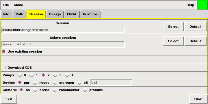
At start-up of 'startbio' a Perl-TK window opens (1) and lets the user choose parameters. Take your time and play with these parameters. Essentially the user is asked about the hardware-setup, whether and how many pumps are attached to the computer, what the interface between computer and the Chemical Microprocessor - ChµP is, whether a new sessions-directory is to be created (if it is already available) and whether the ChµP should be configured or not (2). With the button 'Start' the real ng_biopro-software is launched.
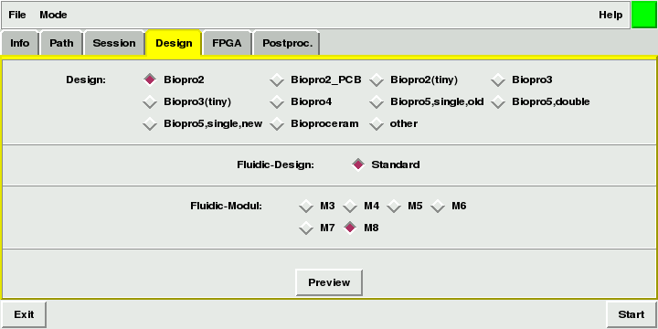
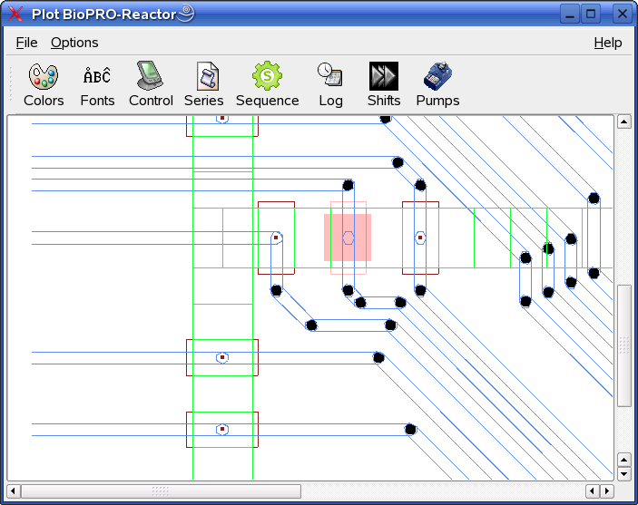
The design-window, which is visible after the starting the ng_biopro-software, the electronic and microfluidic design is presented (3). Zooming into the selected design allows one to see all the details of the electronic and fluidic layer in the BioModule. Shown here are some electrodes (brown rectangles) with one of them selected. This faint pink colour means that the electrode is not yet active but would become positively charged (3.3V or less with two-layer based ChµPs) after activation. The long blue traces are the wires feeding the according electrodes. These wires are isolated and usually show no effects on the chemistry. The fluid channels are shown in green. Visible is a part of a so called "H"-structure which is one of the basic fluidic sub-structures available in the ChµP.
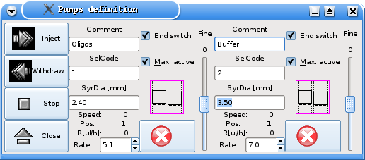
As an example of an often used functionality is the control of the external pumps shown (4). In this case, pumps from the company Micromechatronic Technologies GmbH (Germany) are used which have the exceptional property to support extreme continuous low flow-rates (less than micro-litres per hour) which is a necessity with these micro-fluidic networks. The pumps can be started, stopped and individually stopped. Syringe diameters and flow-rates can be specified. There is also visual status-information available.
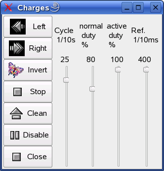
The electrodes shown in the design-window (3) can be activated and deactivated in multiple ways. The method shown here is the basic direct control of individual electrodes. The electrodes affected must have been selected prior to using this popup-window (5). When selecting, these electrodes they will be either in a pink or a light-blue color drawn. Arbitrary many electrodes can be selected (of course not more than 96 or 80 depending on the ChµP). These electrodes can either be activated in one stroke when pressing the 'Stop'-button ('Stop' does not mean 'stop the electrodes' but means 'stop the cycling of the electrodes'). They can be activated in a shift-register-like mode (left or right) when pressing the 'Left'- or 'Right'-button. The sequence of shifting polarities was specified during the selection of the according electrodes. Pressing the 'Invert'-button deactivates all electrodes and reverses the polarity. Pressing either the 'Stop'-, 'Left'- or 'Right'-button reactivates all electrodes again. Simply deactivating all electrodes is done via the 'Disable'-button and cleaning the selection of electrodes is done via the 'Clean'-button.
Three parameters can be adjusted. They steem from the feature that the electrodes not only can be operated in continuous mode (DC) but can also be overlayed by a virtual oscillation to modulate the electrical or electro-chemical effects. This oscillation (which is a rectangular pulsing) has a parameterizable frequency which is determined by the right slider ('Ref'). The parameter 'Normal-duty' specifies the percentage of the period in which the electrodes do have the specified polarity. In the rest time of such a reference-period the electrodes are subjected to the opposite polarity. A 'Normal-duty' of 100% is the default operation. A 'Normal-duty' of 80% and a 'Ref' of 1000 [1/10ms] means that the electrodes are active in 80% of the time which in this example is 80ms of the period of 100ms and exert the reverse polarity from 80ms till 100ms of the reference-period.
The 'Active-duty' is similar to the 'Normal-duty' with the exception that the electrodes are not subjected to the opposite polarity and instead are deactivated during this amount of time.
Combining 'Normal-duty' with 'Active-duty' can result in pretty complex potentials at the electrodes and should only be done by people having understood all the details of the drivers of the field-programmable-gate-array (FPGA) in the ChµP.