The model in a nut-shell

Loosley spoken the model consists of a sea of
micro-controllers which can interact with each other. Because former
research of
BioMIP and others have
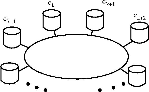
shown how important spatial extension is this sea actually is a
ring of pots of micro-controllers.
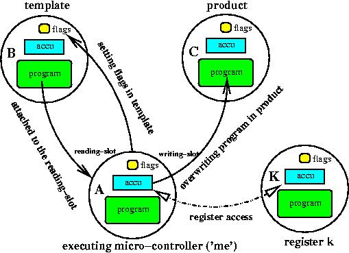
Micro-controllers can interact with each other. Interaction is done
via a recognition procedure.
Each micro-controller can exhibit a recognition pattern, which
is currently the first occuring concatenated sequence of
Site-instructions
in the program. The
attachment procedure tries to find a micro-controller in the vicinity
with an appropriate recognition-site and puts that micro-controller's
address into the reading- or writing-slot,
depending on the instruction which initiated the attachment procedure.
The second recognition-based interaction is realized when transferring
program control from the active micro-controller towards another
micro-controller
(equivalent to a sub-routine call). The third recognition event
is a register access where the foreign micro-controller's accumulator
acts as a local register.
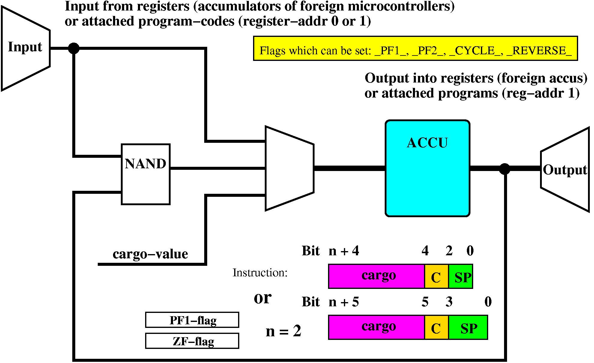
The micro-controller has input-ports, registers or a read-attached
program and output-ports, registers or the write-attached program of a
neighboring micro-controller.
Each instruction is constituted of three parts: the cargo-,
conditional- and special-part.
The cargo-part serves as a parameter for the instruction in the
special-part,
which is executed if the conditional-part, see
table
3 becomes true.

Several instructions are available, see
two variants in
table
1
which are described in table
2.
A further bit is needed to allow for conditional execution. The
instructions
in row J1 of table
1
are
also executed if row J2 is specified and the ZF-flag (accumulator
value 0) becomes active or if row J3 is specified and PF1-flag is
active.
| Execute |
S0 |
S1 |
S2 |
S3 |
| J0 |
End/Cycle |
Site |
Load |
Store |
| J1 |
SetAccu |
Call |
SetFA |
SetFB |
| J2 (ZF) |
" |
" |
" |
" |
| J3 (PF1) |
" |
" |
" |
" |
|
| Execute |
S0 |
S1 |
S2 |
S3 |
| J0 |
SetAccu |
Site |
Load |
Store |
| J1 |
Action |
Call |
SetFA |
SetFB |
| J2 (ZF) |
" |
" |
" |
" |
| J3 (PF1) |
" |
" |
" |
" |
|
Table 1:
Instruction set used. The possible flags are explained
in table 4.
The left instruction table concerns constant program lengths and the
right instruction table is used with variable length sequences. The
default instruction for (J0:S0, left) is Cycle. This
instruction
sets the instruction pointer to address zero. The instruction (J0:S0,
left) can be changed by toggling the _CYCLE_-flag with the SetFB
instruction. In some variants of the instruction set the instruction
SetFB has been replaced by a Goto-instruction.
Only a few instructions do have side-effects during execution, namely,
Action, SetFA,
SetFB and
Site, see table
2. With the instruction
SetFB
the meaning of instruction
End can be changed from stopping
the program immediately to setting the instruction pointer to 0 (
Cycle,
endless loop).
| Acronym |
Description |
| End |
The program stops until it is relaunched again.
Only available with
fixed length programs. |
| Cycle |
The program jumps back to address zero and
continues executing. Only
available with fixed length programs. |
| Load |
Load a value from a register into the
accumulator. The cargo specifies
the address of the register. Register 0 points to the micro-controller
attached at the reading slot. Register 1 points to the micro-controller
attached at the writing slot. With no micro-controller attached a
search is ignited. Prepending Site-instructions increase the
specificity of register-addressing. With no Site-instructions
before and accessing register 0 or 1 a random search is done. If no
suitable micro-controller is found this instruction is ignored. |
| Store |
Store the accumulator in a register. The cargo
specifies the address
of the register. Register 1 points to the micro-controller attached
in the writing slot. Register 0 points to the micro-controller attached
at the reading slot. With no micro-controller attached a search is
ignited. Prepending Site-instructions increase the
specificity
of the register-addressing. With no Site-instructions before and
accessing
register 1 or 0 a random search is done. If no suitable
micro-controller
is found and address 1 is accessed the program is stopped to save
time-slices. |
| Call |
Transfer execution to the micro-controller
specified in the cargo-part
of this instruction. Accumulator and attachment slots are transferred
to the new micro-controller. The current program is stopped after
this call.
Prepending Site-instructions increase the specificity of the
micro-controller addressing, these Site-instructions are
combined
with the cargo-part of the Call-instruction to one big
virtual
recognition-site. If no appropriate micro-controller found the
instruction
is ignored. |
| SetAccu |
Preset the accumulator with the value provided
by the cargo-part. |
| Site |
Define a recognition-site, either to be
recognized by others or to
actively attach to other micro-controllers. Used with instructions Call,
Load and Store. |
| SetFA |
If a machine is attached at the reading-slot
(e.g. after accessing
register 0) then certain flags can be set in this machine, see
description
of table 4, left part. |
| SetFB |
Set flags in the executing machine. See table 4,
right part, for a description of these flags. |
| Action |
This command is only available when using
variable length program
sequences.
See table 7 for a description of
the
possible actions. |
| Goto |
This instruction was superseeded by the SetFB
instruction.
It set the instruction pointer counter (IPC) to the address given
in the cargo-part of the instruction. |
Table 2: With a
special command (SP) width of two bits (and borrowing a case
from the conditional part) these special instructions can be encoded.
| Bit 1 |
Bit 0 |
Meaning |
| 0 |
0 |
Instructions are executed always |
| 0 |
1 |
Instructions are executed always and do have conditional
equivalents |
| 1 |
0 |
Only executed if the ZF-flag (ACCU with value 0) is set |
| 1 |
1 |
Only executed if the PF1-flag (via other controllers or from
outside)
is set |
Table 3: Conditional
part of an instruction. Instructions can be executed if
certain conditions are fulfilled, like a zero-value of the accumulator
(ZF-flag) or the flag PF1 set in the status-register of a
micro-controller.
| Flag |
Meaning |
| _PF1_ |
general communication |
| _PF2_ |
set if this micro-controller is invisible
(protection) |
Setting flags A at a foreign micro-controller, using the special
command SetFA. If no micro-controller is attached the
instruction is
ignored. |
| Flag |
Meaning |
| _CYCLE_ |
End-instruction means jumping to
address 0, only valid with
fixed length programs |
| _REVERSE_ |
reading and writing goes backwards |
These flags B can be set with the special command SetFB. |
Table 4: All flags
available for a cargo-width of two are shown here. Of course,
with a cargo-width larger then two, further flags could be defined.
Flags A (left table) are always available at a foreign micro-controller
which is attached via the reading-slot and Flags B (right table) are
situated in the own micro-controller.
| Action |
Description |
|
| Ligate (00) |
If there are
two machines located, one in the reading and another
in the writing-slot, the program of the machine in the writing slot
is appended to the program in the reading-slot. The machine in the
writing slot is invalidated after that and will be replaced by a newly
created machine at the next simulation round. |
| Split (01) |
If there are t
wo machines located in the reading and writing-slot
the program of the machine in the writing slot is replaced by the
program right after the current remote instruction pointer (typically
after the recognition site). The program in the reading slot is
shortened
accordingly. |
| CopyMask (10) |
Copy the ma
chine-mask from the
reading-slot-machine into the machine's machine-mask attached at the
writing-slot. |
| CopyLen (11) |
Copy the len
gth of the machine in the reading-slot into the machine
of the writing-slot, which resembles a truncation or an elongation. |
| Release reading-slot (100) |
If a machine is attached at the reading-slot it
will be released via
this action. |
| Release writing-slot (101) |
If a machine is attached at the writing-slot it
will be released via
this action. |
Table 5: Possible action-commands. Depending on the
number of bits in the cargo-part of the instruction the shown actions
can take place.
Topology

It is now common sense that spatially resolved systems are
important
for evolution to escape parasitism, to maintain sensible information
and to increase diversity in the population, see e.g. [
8,
3,
33]
or experimental work [
55,
6,
12,
54]. A question
remaining is the optimum spatial dimensionality of the system.
Experiments
showed that the length of evolutionary avalanches and thus the
diversity
in the system is best in the one-dimensional case, [
1],
meaning space is spanned along a ring-topology, see Figure .
Currently two-, one- and half-dimensional spaces can be investigated.
We speak of half-dimension if the number of neighbors is one,
communication
along the ring can only proceed in one direction.
In the simulations reported the number N of containers is between
16 and 4096 and the number m of processors per container between
8 and 32. Communication is restricted to neighboring containers. The
communication between containers is organized such that the
micro-controllers
do have read- and write-access to the micro-controllers of the
neighboring
containers as well as to the micro-controllers of the own container.
This, for example, gives with two neighboring containers and 16
micro-controllers
per container 47 micro-controllers to exchange information with.
Information
exchange means access to the others program-code, accumulator or status
flags-section.
A container is a well-stirred reaction vessel with no further spatial
organization. Each processor is able to issue arbitrary many
Site instructions, see Table
1.
Several
Site instructions are concatenated, if they are
issued in
direct sequence, to create a larger and thus more specific recognition
site.
These extracted recognition sites are stored in a content-addressable
memory to allow for a rapid attachment procedure. Of course, several
other possibilities to distribute the recognition-sites do exist and
even a cyclic redundancy check fingerprint (CRC16) could be used to
identify the micro-controller programs.
In addition to direct communication, micro-controllers are picked
at random from time to time and are exchanged with micro-controllers
from neighboring containers. This resembles a diffusive process in
the system. In the experiments reported though no diffusive exchange
was undertaken.
A minimum replicator program
Shown in Table
5
are two minimal replicator program sequences one for
the fixed-length sequences case and the other for variable-length
sequences. It is obvious that at least two of these programs have to be
in a neighborhood to allow both to replicate each other. Larger
networks are feasible as well but less probable. Only have two programs
which are able to replicate each other is an idealistic view.
Realistically several such programs must exist because the other
micro-controllers are active as well and easily can destroy these two
starting replicators.
| Bits |
cargo |
C |
SP |
| Site |
xx |
00 |
00 |
| Load |
00 |
00 |
10 |
| Store |
01 |
00 |
11 |
| End/Cycle |
- |
00 |
00 |
|
| Bits |
cargo |
C |
SP |
| Site |
xx |
- |
00 |
| Load |
00 |
- |
10 |
| Store |
01 |
- |
11 |
|
Table 5: A minimum replicator
program for fixed program lengths
is shown.
The bits (xx) in the cargo-part of the Site-instruction are
arbitrary but need to be stabilized throughout evolution. The bits
of the cargo-part of the End-instruction (left part) are not
evaluated. The total number of bits needed to be at the correct
position
with the correct value during evolution is 22.
With variable length sequences and a machine-mask of 0x3, (right part),
12 bits and a
program length
of three instructions have to be found and maintained by the dynamics.
Even if one omits the requirement of a univeral computability at
least 12 bits are required to be stabilized against
evolution and ten bits have to be found
de novo, actually these are twenty
bits
because we do need two micro-controllers for a replication cycle.

 Several instructions are available, see
two variants in table 1
which are described in table 2.
A further bit is needed to allow for conditional execution. The
instructions
in row J1 of table 1
are
also executed if row J2 is specified and the ZF-flag (accumulator
value 0) becomes active or if row J3 is specified and PF1-flag is
active.
 It is now common sense that spatially resolved systems are
important
for evolution to escape parasitism, to maintain sensible information
and to increase diversity in the population, see e.g. [8,3,33]
or experimental work [55,
6,
12,
54]. A question
remaining is the optimum spatial dimensionality of the system.
Experiments
showed that the length of evolutionary avalanches and thus the
diversity
in the system is best in the one-dimensional case, [1],
meaning space is spanned along a ring-topology, see Figure .
Currently two-, one- and half-dimensional spaces can be investigated.
We speak of half-dimension if the number of neighbors is one,
communication
along the ring can only proceed in one direction.
In the simulations reported the number N of containers is between
16 and 4096 and the number m of processors per container between
8 and 32. Communication is restricted to neighboring containers. The
communication between containers is organized such that the
micro-controllers
do have read- and write-access to the micro-controllers of the
neighboring
containers as well as to the micro-controllers of the own container.
This, for example, gives with two neighboring containers and 16
micro-controllers
per container 47 micro-controllers to exchange information with.
Information
exchange means access to the others program-code, accumulator or status
flags-section.
A container is a well-stirred reaction vessel with no further spatial
organization. Each processor is able to issue arbitrary many
Site instructions, see Table 1.
Several Site instructions are concatenated, if they are
issued in
direct sequence, to create a larger and thus more specific recognition
site.
These extracted recognition sites are stored in a content-addressable
memory to allow for a rapid attachment procedure. Of course, several
other possibilities to distribute the recognition-sites do exist and
even a cyclic redundancy check fingerprint (CRC16) could be used to
identify the micro-controller programs.
In addition to direct communication, micro-controllers are picked
at random from time to time and are exchanged with micro-controllers
from neighboring containers. This resembles a diffusive process in
the system. In the experiments reported though no diffusive exchange
was undertaken.


