


As a step towards artificial cells, we investigated whether the nice features of traveling concentration wave fronts could be transferred to a stable stationary replication wave. This could form the basis of a self-maintaining non-equilibrium replication process. The more obvious way to do this, by balancing the traveling wave velocity along a channel with an opposing fluid flow, was investigated in McCaskill´s labs early in the ‘90s [1]. Because of the parabolic profile of velocities across a capillary, the concentration wave front no longer remains perpendicular to the channel walls and lateral diffusion plays an important role in determining the front velocity under flow. More seriously, an exact balance of the modified wave velocity with flow rate is required, and proves experimentally unstable. A solution is to use a wedge-shaped microreactor (we also call this "fan"-reactor) has been designed to allow ongoing chemical replication with a constant gradient in a microfluidic system[2]. The fan-flow reactor also provides a gradient of through-flow and hence material exchange rates.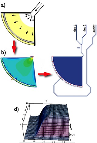
The right scheme showing principle of the fan reactor – from concept to mask design. The black arrows in the schematic view a) show the direction and magnitude of fluid flow. The pale yellow region is where the amplification reaction has sufficiently low product depletion from flow to take significant hold. Propagation of amplified material towards the center of the fan is exactly compensated by the flow for any value of the concentration gradient at a particular radius. Hydrodynamic simulation for design optimization b) we have done before led to the basic design of the microreactor system as shown in c). We used our soft-lithography technique to build up this microfluidic system. The microreactor dimensions are as follows: inlet channel width 40-60 µm; outlet channel width 300 µm.; radius of wedge-shaped reaction chamber 4.5 mm; depth of the reactor chamber as well as the main inlet and outlet channels are up to 110 µm; 21 small reactor-outlet channels (red coloured): width 20 µm (25 µm depth). The radial vs time template concentration for the SDA test reaction system from kinetic simulation is shown in d). The movie in the upper left corner shows the experimental validation of the simulated design of the "fan"-microreactor.